The Case of the Low Power (Only) Antenna
The goal was to home-brew the most efficient multi-band antenna possible for my aging aluminum bodied motorhome. But the result was an antenna that worked well with 1 milliwatt and refused to work with 10 watt or more!
I read all the books, especially the section on mobile antenna efficiency.
I knew the design would:
-
The overall length of the antenna was to be 12 feet. The bumper on this 1973 Dodge motorhome was less than a foot off the ground (terrible to mount so low when you are going for efficiency, but it was the only option available.)
-
Place the loading coil above the roof line (it would not be along the wall). The bottom section of the antenna was 7 feet long. That’s as long as I could make it and still be able to reach the taps to change bands without a ladder.
-
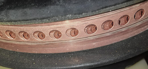
The loading coil was home made from PVC pipe and had a 4 inch diameter and 1 foot long (not counting the pvc end caps.)
-
The loading coil had a low pitch – only 3 turns per inch which kept the interwinding capacitance very low (and the self resonance very high).
-
The loading coil was wound from #10 copper wire.
-
The bottom section of the mast (from feed point to loading coil) was made with 1 inch copper pipe.
-
The base insulator of this antenna was a 2 inch diameter cylinder of solid plastic. I don’t know what type it was (pvc, abs, acrylic, etc) but it easily passed the microwave oven test for efficiency.
-
I would spare no expense to get the most efficient multi-band base fed center loaded antenna I could.
With a bumper mounted antenna this long it would be ridiculous to think that the base mount could hold the antenna up against 55 mph winds, so I mounted a galvanized steel tv mast bracket to the aluminum body of the motorhome at approximately 5 feet above the bumper, which placed this bracket just below my eye level.
To insulate the antenna mast from the metal bracket (and the aluminum body of the motorhome) I used a 4 cm length of heater hose. I slit the heater hose along its length and wrapped it around the 1 inch copper pipe, and this then went into the Radio Shack obtained tv antenna wall bracket. I was happy that the antenna was now very sturdy and did not wiggle.
I installed a Hustler mobile antenna spring at the top of the loading coil so the top whip could bend over when I drove under low-hanging trees.
When it was all constructed, I used an Autek RF-1 impedance meter to help me quickly find the coil tap that was best for 40m cw, and was happy to see that the impedance was very low, showing that I had achieved the efficiency goal. Then I adjusted the input matching coil tap to get the impedance up to 50 ohm for my coax connection.
Every time I keyed up, the SWR meter showed infinite.
-
Was something failing in my home-made loading coil?
-
I unscrewed the loading coil and mounted one of my large selection of Hustler brand loading coils. No difference could be seen. Frustrated, I tried more, 75m, 30m, and 20m. Every one of them showed the same results; better than 1.5:1 with the Autek impedance meter, and “infinite” with the Yaesu, and both Ten Tecs.
-
-
Could it be corona discharge?
-
I have seen that before, but only when running high power, like 600 watts.
-
-
The coax was breaking down under voltage?
-
I have seen that before also. Easy to test, just swap it out – same results.
-
-
Arcing between some part of the antenna and the vehicle?
-
To check for arcing, I drove the motorhome away from city lights and city noises. I could not hear or see any arcing. Besides… this problem was occuring with as little as 10 watts, so I was very skeptical.
-
-
Loose hardware?
-
Every screw, crimp connector, bolt, nut was replaced.
-
-
Excessive harmonics or spurious emissions from my transmitter?
-
Remember this type of antenna will only have a good match to 50 ohm feedline at one frequency. If there was a serious harmonic problem or spurious emissions from the transmitter, they would be on frequencies with a high swr. But “infinite” ?
-
Easy to test, get another transmitter that’s known to be good. Yep, same symptoms as the first rig 🙁
-
-
Had my base insulator absorbed enough moisture to cause a problem?
-
I disassembled the antenna again and subjected the plastic cylindrical base insulator to the microwave test – it passed again.
-
Check again with the impedance meter and I had 1.2:1 on 40m CW. Now I was getting mad.
I thought I was a well educated RF engineer with a good sense of troubleshooting and root-cause analysis, so this “low power only antenna” was really getting to me.
So what could be behaving differently at low power and “high power”? Really baffling is that “high power” in this case meant 10 watt! The Autek RF-1 meter used something on the order of 1 milliwatt. I was beginning to wonder at what power this antenna changed its SWR. Also, was it a sudden change from 1.2:1 to infinite? Like was 1 watt ok and 1.001 watt was ‘forbidden’ ? Or was it some gradual change?
Unfortunately, I did not have any equipment to make this kind of test. While I did have a 80 dB step attenuator available, I did not have any 10 dB or 20 dB attenuators that could handle 10 watt input.
This antenna had consumed all of my evenings and weekends for two weeks now. I was so mad that I was willing to risk destroying some equipment if it would help me learn the real cause of the problem.
So I ordered 30m roll of RG8, installed connectors and ran it inside the house to my Heathkit SB-1000. What was I going to do with that? It’s called the smoke test!
I set the rig for 40m CW, tuned up the amp into a Heathkit Cantenna dummy load then switched it all over to the coax running out in the yard to the motorhome antenna. I keyed up the rig and slowly turned up the power until the power meter showed 400 watt. Of course since this problem antenna was no where near a 50 ohm load, the power meter could never be correct, but it was all I dared to risk my amplifier.
Happy happy happy. I was never so happy to see smoke gushing out of something I worked so hard to design and construct! There was no doubt now that I had found the cause! And once we find the cause we can most usually design a fix!
I shut down the rig and left the SB-1000 amplifier on standby to cool. Oh, how I wish I had a camera to document that smoking antenna component.
I was mad and extremely happy. I was so happy I found the cause of all this trouble and wasted evenings.
I was mad that I was unable to figure out the cause the moment that the problem was discovered. I knew the answer, it just was not in the correct part of my brain at that time. And it was such an inexpensive fix!
For decades I have heard people so wrongly say that “you’re safe in your car during a lightning storm because the tires insulate you.” Then I explain to them that your are safe in a car because it forms a faraday shield. The tires can not protect you because the manufacturers add carbon black to the mix to make the tires conductive so that the car will not behave as a van degraff generator.
So I had all the information needed to fix this problem already in my head long before I started making this “ultimate multiband mobile antenna”.
I already knew that car tires are semiconductors; the impedance of the car tire varies greatly with the voltage applied.
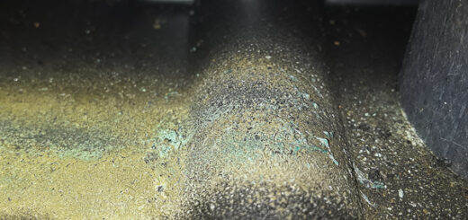
God knows why the car heater hose has this characteristic as well, but the piece I had was, and like modern car tires, a voltage dependent semiconductor. There, right at eye-level holding my ultimate mobile antenna securely to the motorhome, the piece of car heater hose that I used as an insulator was still producing a horrible smelling smoke that was now making me smile.
So the very low voltage from the Autek impedance meter (around 223 millivolts at the input to the matching network at the base feed) was low enough that the car heater hose did not exhibit any significant change in conductivity. But that 10 watts, the minimum my Yaesu would do, was enough to turn the heater hose far into its conductive state.
The heater hose was removed and a piece of pvc pipe put in its place. Now I could enjoy campground evenings on 40, 30, and 20 meter cw.